
Master Information Block (MIB) in LTE – Complete Technical Guide
Introduction to Master Information Block (MIB)
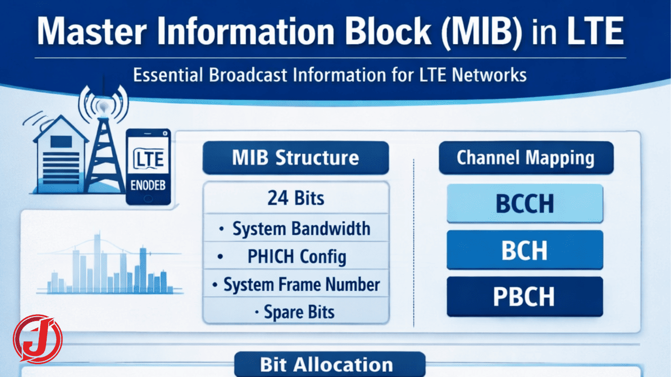
The Master Information Block (MIB) in LTE is the most fundamental broadcast message transmitted by the eNodeB (base station). Defined under the standards of the 3rd Generation Partnership Project, the MIB contains essential system-level parameters that every User Equipment (UE) must decode before accessing the network. Without successfully decoding the LTE MIB, a device cannot proceed with further signaling procedures such as reading System Information Blocks (SIBs) or initiating an RRC connection.
During the initial cell access procedure, the UE first synchronizes with the network by detecting Primary and Secondary Synchronization Signals (PSS/SSS). These synchronization signals allow the UE to identify the Physical Cell ID and achieve time and frequency alignment. Once synchronization is achieved, the UE proceeds to decode the Physical Broadcast Channel (PBCH), which carries the MIB. This step is mandatory before decoding any other control or data channels.
The MIB is transmitted periodically and continuously, irrespective of whether any UE is connected to the cell. It ensures that any device entering coverage can immediately acquire critical information such as system bandwidth, frame timing, and PHICH configuration. Because it acts as the gateway to all other LTE signaling, the MIB plays a central role in LTE network accessibility, reliability, and performance optimization.
Channels Carrying the MIB
The MIB flows through multiple channel layers in LTE protocol architecture:
Logical Channel – BCCH
The Broadcast Control Channel (BCCH) carries system control information intended for all UEs in the cell. MIB belongs to BCCH because it is common broadcast information.
Transport Channel – BCH
The Broadcast Channel (BCH) is responsible for transporting the MIB from higher layers to the physical layer. It is specifically designed for broadcasting essential system information.
Physical Channel – PBCH
The Physical Broadcast Channel (PBCH) transmits the MIB over the air interface. It ensures high reliability through robust coding and repetition mechanisms.
RLC Mode – Transparent Mode (TM)
The MIB uses Transparent Mode at the RLC layer, meaning no additional retransmission or segmentation occurs. This minimizes latency and ensures efficient broadcast delivery.
Basic Characteristics of LTE MIB
The LTE MIB has the following technical characteristics:
- Size: 24 bits (payload only)
- Resource Requirement: 6 Resource Blocks (72 subcarriers)
- Location in Resource Grid:
- Subframe #0
- Second slot
- OFDM symbols 0, 1, 2, and 3
- Modulation Scheme: QPSK
- Channel Coding: Tail-bit convolutional encoding
- Rate Matching: 1/16 repetition coding
The use of QPSK modulation ensures robustness under low Signal-to-Noise Ratio (SNR) conditions. Additionally, heavy repetition coding guarantees extremely high decoding probability, as MIB carries critical network parameters.
MIB Message Structure (As per 3GPP TS 36.331)
According to the LTE specification defined in 3GPP TS 36.331, the MIB structure is:
MasterInformationBlock ::= SEQUENCE {
   dl-Bandwidth ENUMERATED {n6, n15, n25, n50, n75, n100},
   phich-Config PHICH-Config,
   systemFrameNumber BIT STRING (SIZE (8)),
   spare BIT STRING (SIZE (10))
}
This structure defines the essential broadcast parameters required for UE operation.
Bit Allocation Inside 24-bit MIB Payload
The 24-bit MIB payload is divided as follows:
- 3 bits – System bandwidth
- 3 bits – PHICH configuration
- 1 bit – PHICH duration (Normal/Extended)
- 2 bits – PHICH Ng value
- 8 bits – System Frame Number (SFN)
- 10 bits – Reserved (spare bits)
This compact design ensures minimal overhead while delivering maximum essential information.
Role and Significance of Each MIB Field
System Bandwidth
This field tells the UE the total downlink bandwidth of the cell (e.g., 1.4 MHz to 20 MHz). Without this information, the UE cannot properly decode other physical layer channels.
PHICH Configuration
PHICH parameters indicate how Hybrid ARQ acknowledgments are transmitted. The Ng value determines the number of PHICH groups, while duration specifies control channel mapping. This information is essential for decoding PDCCH and DCI messages.
System Frame Number (SFN)
The 8-bit SFN assists the UE in frame timing synchronization. It helps detect the 40 ms MIB boundary and supports periodic time alignment.
Spare Bits
Reserved bits provide flexibility for future LTE standard enhancements without changing the MIB size.
CRC and Antenna Configuration Information
A 16-bit CRC is attached to the MIB payload. This CRC is scrambled with an antenna-specific mask. By decoding the CRC, the UE can determine the number of transmit antennas used by the eNodeB (e.g., 1, 2, or 4 antennas). This information is critical for MIMO configuration.
PBCH Transmission Mechanism
Generation Periodicity
A new MIB is generated every 40 ms when SFN % 4 = 0.
Transmission Periodicity
PBCH transmits every 10 ms (each radio frame). The same MIB content is repeated across four consecutive frames.
Sub-buffer Transmission
The encoded PBCH produces 960 QPSK symbols. These are divided into four sub-buffers of 240 symbols each and transmitted across RF-0 to RF-3.
Redundancy Versions
The first transmission carries the new MIB, while subsequent transmissions carry redundancy versions to improve decoding reliability.
Physical Layer Processing of MIB
- CRC Generation: 16-bit CRC added and scrambled.
- CRC Attachment: 24-bit MIB + 16-bit CRC = 40 bits.
- Convolutional Encoding: Produces three 40-bit streams.
- Rate Matching: 120 bits repeated 16 times → 1920 bits.
- Scrambling: 1920-bit scrambling applied.
- QPSK Modulation: 1920 bits converted into 960 QPSK symbols.
This heavy redundancy ensures extremely high reliability for LTE broadcast signaling.
Resource Mapping of PBCH
PBCH occupies the central 6 PRBs of the system bandwidth and is located in Subframe 0. It uses the first four OFDM symbols of the second slot. Each PBCH transmission is independently decodable, allowing faster UE acquisition.
MIB Acquisition by UE
Best Case
If UE starts decoding at RF-0, it identifies the 40 ms boundary in 40 ms.
Worst Case
If UE begins at RF-1, it may require up to 70 ms to detect the boundary.
This mechanism guarantees deterministic acquisition timing.
Importance of MIB in LTE Network
The MIB is the first and most critical broadcast message in LTE. It enables:
- Decoding of PDCCH and SIBs
- Identification of system bandwidth
- Timing synchronization
- Preparation for RRC connection setup
Without MIB, LTE network access is impossible.
LTE MIB vs 5G NR MIB Comparison
In 5G NR (as defined by 3rd Generation Partnership Project):
LTE MIB
- 24-bit payload
- 40 ms generation periodicity
- Fixed bandwidth signaling
- Transmitted via PBCH in Subframe 0
5G NR MIB
- Transmitted within Synchronization Signal Block (SSB)
- 80 ms transmission periodicity
- Includes subcarrier spacing parameter
- Flexible frequency mapping
- Optimized for scalable numerology
NR design improves flexibility and supports diverse deployment scenarios.
Conclusion
The Master Information Block (MIB) in LTE is the foundation of cellular communication. It provides the UE with indispensable parameters such as system bandwidth, PHICH configuration, antenna setup, and system frame number. Transmitted through BCCH → BCH → PBCH using QPSK modulation and strong repetition coding, the MIB ensures ultra-reliable broadcast delivery.
For telecom engineers, RF planners, and protocol developers, understanding LTE MIB generation, encoding, mapping, and acquisition is crucial for network optimization and troubleshooting. In essence, MIB is the first handshake between the LTE network and the user device—making it the cornerstone of LTE system design.